Article

ViPER+: Vehicle Pose Estimation Using Ultra-Wideband Radios for Automated Construction Safety Monitoring

1
Department of Computer Science, University of Houston, Houston, TX 77004, USA
2
Durham School of Architectural Engineering and Construction, University of Nebraska-Lincoln, Lincoln, NE 68588, USA
*
Author to whom correspondence should be addressed.
Appl. Sci. 2023, 13(3), 1581; https://doi.org/10.3390/app13031581
Submission received: 28 November 2022 / Revised: 5 January 2023 / Accepted: 12 January 2023 / Published: 26 January 2023
(This article belongs to the Section Civil Engineering)

Abstract

:
Pose estimation of heavy construction equipment is the key technology for real-time safety monitoring in road construction sites where heavy equipment and workers on foot collaborate in proximity. Ultra-wideband (UWB) radios hold great promise among various sensing technologies for providing accurate object localization in indoor and outdoor environments. However, in a road construction environment with heavy vehicles and equipment, the performance of UWB radios drastically declines because of blockages in the transmission signal between the transmitter and receiver causing Non-Line of Sight (NLOS) situations. To address this deficiency, our study presents a real-time pose estimating system called ViPER+ that can overcome NLOS situations and accurately determine the boundary of heavy construction equipment with multiple UWB tags attached to the surface of the equipment. To remove the impact of NLOS signals, we introduced an input correction method prior to localization to correct the input of the localization algorithm. Evaluation of ViPER+ in a real construction environment indicates that embedding NLOS detection technique in UWB-based pose estimation resulted in 40% improvements in location accuracy and 25% improvement in update rate compared to its previous implementation (ViPER).

1. Introduction

The construction industry is known for being hazardous and responsible for a significant number of workplace fatal and non-fatal injuries. According to the Occupational Safety and Health Administration (OSHA), the construction industry was responsible for 971 (20.7%) of the 4674 work-related deaths that occurred in the US private sector in 2017 [1]. The OSHA report estimates that the four most common safety hazards—falls, struck by an item, electrocution and caught-in/between could be avoided, potentially saving 582 lives. Particularly at road building sites, workers are regularly exposed to possible safety hazards from moving machinery and vehicles. The National Institute for Occupational Safety and Health (NIOSH) estimates that there were an average of 123 work-related fatalities at road construction sites each year from 2003 to 2017, totaling 1844 deaths over that period [2]. From the investigation carried out by NIOSH [2] between 2011 and 2017, 76% of all deaths occurred in transportation-related incidents, and 60% of these transportation-related deaths occurred in work zones from being struck by a vehicle or mobile equipment (pickup trucks and SUVs—151 worker deaths, automobiles—129, semi-trucks—124, and dump trucks—82). According to this report [3], nearly half (305 instances) of the 639 worker deaths on road construction sites from 2003 to 2007 were caused by being struck by a vehicle or mobile machinery, with construction-related vehicles killing more workers (38%) than vehicles not tied to construction operations (33%). In all, while there are various causes responsible for accidents on construction sites, these statistics indicate that there is an urgent need to prevent struck-by accidents on road construction work zones.
For the prevention of safety hazards in general, various efforts such as the enforcement of safety regulations [4], provision of safety training and monitoring, and creation of work zone safety planning guidelines [5] have been made in the construction industry. OSHA provides comprehensive regulations and recommendations for the safe execution of construction projects [4]. Construction workers receive training, such as OSHA 10-h and OSHA 30-h, to gain essential knowledge in work-related safety and health issues and learn how to avoid them during construction operations. During the planning stage, road construction projects create Internal Traffic Control Plans (ITCPs) to manage operations in a work zone where vehicles, construction machinery, and workers on foot operate in close proximity [5]. A study shows that careful preparation and utilization of ITCP can reduce the risk of safety hazards in work zones [6]. After the construction starts, safety experts, called competent persons, are deployed to monitor ongoing activities to identify unsafe situations and provide prompt interventions to workers and operators. The role of a competent person is critical in ensuring safety because workers are not able to recognize 33–57% of potential safety hazards from cluttered construction sites [7,8,9].
Despite such efforts by the construction industry, there are still a great number of fatalities and injuries occurring, with one of the reasons being the dynamic and complex construction site conditions. For a large construction site, a limited number of competent persons cannot observe multiple simultaneous activities throughout their entire operations. Therefore, even a safety expert with adequate knowledge and experience cannot fully recognize all the unsafe situations that appear in different locations. Such challenges associated with monitoring construction operations form the basis of recent research direction categorized under the term “automated safety monitoring”. Automated safety monitoring is one of the potential methods for continuously monitoring vast work zones. It acquires and analyzes digital data about workers, equipment, vehicles, and work zone conditions promptly which is not possible with current practices, such as ITCP safety planning and manual work zone monitoring.
To automate this process, recent studies have created systems to track the position of workers inside construction sites utilizing different wireless technologies such as Bluetooth [10,11], ultra-wideband (UWB) [12,13], and radio frequency identification (RFID) [14]. Similarly, several approaches have been developed in the research community to track vehicles in construction sites using wireless technologies such as Bluetooth [15], Global Positioning System (GPS) [16], and UWB [17]. Among these wireless technologies, UWB radios are particularly promising for providing precise and feasible localization due to their impulse-shaped signals and high bandwidth. The recent generation of UWB systems can provide precise location tracking with an accuracy of up to 2–15 cm in a controlled environment without the need for extensive infrastructure [18]. These UWB technologies show great potential for automatically detecting hazardous situations in road construction sites through the accurate tracking locations of workers and equipment. Previous studies [12,13] have shown that UWB technology has the potential to provide precise location tracking of resources in construction sites.
Despite UWB radios being capable of high-accuracy localization, developing a safety monitoring system using UWB radios faces critical challenges when deployed in construction sites. A non-Line of Sight (NLOS) situation can occur when the presence of trucks, loaders, and other obstacles in the field can obstruct or deflect the signal as it travels from the transmitter to the receiver. The accuracy of the UWB localization drops when exposed to NLOS situations [19,20,21,22]. Previous works on vehicle localization and pose estimation were outside of construction sites [17,23,24,25,26,27,28,29] without considering the NLOS situations occurring due to construction equipment. Without a pose estimating robust against NLOS situations in construction sites, the pose of heavy construction equipment cannot be accurately determined. Therefore, our study presented in this paper attempts to develop a real-time system that can resolve the impacts of NLOS situations and accurately determine the pose of heavy construction equipment.
For that, we developed a framework that reduces the impact of NLOS signals in both localization and pose estimation by proposing an NLOS error correction method before conventional TDOA location estimation. Our contributions in this paper include (1) measuring the impact of the NLOS situation caused by trucks and heavy equipment on localization and pose estimation output, and (2) developing an automated evaluation and reduction of NLOS effects on localization in a road construction environment.

2. Literature Review

2.1. Automated Safety Monitoring Systems for Real-Time Environments

Studies report that construction workers may not recognize 33–57% of potential safety hazards from construction sites [7,8,9]. To prevent workers’ exposure to unsafe conditions, OSHA requires construction projects to deploy safety experts called “competent persons” who can detect existing or predictable safety hazards and have the authority to correct them [30]. The competent person’s roles include observing conditions and activities of the construction site, identifying potential safety hazards, and correcting problematic conditions or behaviors. Like safety monitoring, construction safety planning is also an essential task in proactively eliminating potential hazards before construction starts. During safety planning, locations and times of potential safety hazards should be thoroughly identified manually [31] or automatically [32,33]. Highway and bridge construction projects create project-specific safety planning called Internal Traffic Control Plans (ITCPs) to direct construction traffic in work zones and separate heavy equipment from workers on foot [6]. However, even with proactive safety planning, onsite activities still require frequent site visits followed by a labor-intensive visual analysis that can be highly error-prone. Similarly, an ITCP presents a static plan that requires site visits and manual observation. The execution of the static ITCP can potentially benefit by incorporating real-time locations of workers, equipment, and vehicles that dynamically move during construction.
To overcome the significant limitations of traditional manual safety monitoring, recent studies have proposed the use of sensing technologies. The use of sensing technologies aims to enable real-time communication through automated, continuous, and accurate monitoring of construction site conditions. Fang et al. [14] implemented construction safety management using building information modeling (BIM), RFID sensors, and cloud communication. The proposed solution was able to divide the environment into different zones and track the presence of workers inside the zones. The coarse localization provided by this solution can be used for some safety applications; however, it does not fulfill all requirements such as proximity detection.
Lee et al. [34] used ultrasonic and infrared sensors to create another automatic safety monitoring system. They used a mobile sensing device to alert workers (without sensor tags) approaching predefined hazardous areas in construction sites. However, the functionality of the system only relied on proximity estimation between the workers and sensing devices. This means that it did not provide construction and safety managers with comprehensive information about the activities of workers and the construction environment.
Park et al. [10] created a Bluetooth low energy (BLE)-based indoor localization solution to monitor workers in a building. In their work, they used 40 BLE beacons to cover a 27 × 39 m field. They later improved the accuracy of their localization method by fusing the output of the localization with motion sensors and building geographic information [11]. The first challenge with this approach is the deployment of localization infrastructure. Placing a large number of BLE beacons through the whole area is not plausible in all construction sites (e.g., it is impossible to place a beacon in the middle of the road where trucks and loaders are passing). Furthermore, fusing data from multiple sensors for localization is not practical in all entities. For example, tracking an excavator with sophisticated movements (e.g., rotation, displacement) is only feasible if the movements are limited, which does not apply to all construction sites.
Researchers have found UWB-based systems to demonstrate high potential for localization technology. Carbonari et al. [12] developed a prototype for proactive safety management and real-time alert of potential overhead hazards using UWB technology. They placed four UWB anchors at the corner of a 30 × 10 m field. The system tracks the location of workers carrying UWB tags and sends an alarm if the location is within the “red area” representing hazardous zones on the map. Prior research with the Zebra Sapphire DART UWB system in a construction-like scenario was able to achieve tens of centimeters of localization accuracy [13,35]. The UWB system used in this study, however, requires wires to connect the anchors to the hub making it inappropriate for real-world construction scenarios. There is a newer generation of fully wireless UWB systems which have not been extensively tested in a construction environment. UWB localization based on Ubisense chip was reported to have achieved tens of cm of accuracy even with mobile objects [36,37]. Researchers have reported accuracy of up to 2 cm in industrial applications with Decawave UWB system [18] and some other work has reported Decawave UWB to be superior to BeSpoon UWB [38]. Thus, the newer generation of UWB systems holds a lot of promise in introducing precise location tracking but they have not been customized and tested for the unique constraints of construction sites and environments.

2.2. Vehicle and Equipment Tracking Using Ultra-Wideband Radios

In addition to monitoring workers, tracking heavy vehicles and equipment is also critical for automated safety monitoring in road construction environments. There have been several classes of studies on utilizing UWB radios for equipment tracking that can be categorized into relative tracking, absolute tracking, and tracking with auxiliary sensors. In the case of relative tracking, since only the relative position of UWB radio nodes is used, no infrastructure needs to be installed in the environment. Researchers used the idea of relative ranging to avoid collision of tower cranes [39]. Each crane can be equipped with one or more UWB tags. Any two tags which are not on the same crane can be paired in the monitoring system. If any range measurement between any pairs reports a value below a specific threshold, the monitoring system alerts the operators. Building a construction safety system is possible using only the range measurements that monitor the distance between workers and vehicles in construction sites [40]. Furthermore, using two tags on each vehicle and measuring the range between any possible pair of tags across vehicles can provide a relative positioning system for each vehicle along with its relative speed and direction [41].
Absolute tracking systems require the installation of UWB infrastructure which consists of fixed anchor nodes placed on known positions in the environment. These systems estimate the location of the entity in the field instead of their relative distances. Tracking the location of entities provides more information about the construction environment which is beneficial for some safety tracking applications. Absolute tracking systems have previously tracked the location of the vehicle by installing one UWB radio on the vehicle [42]. However, tracking the orientation of vehicles requires more than one tag [17,43,44]. The presence of vehicles and equipment in construction sites may distort the UWB signals sent from the tags. They can also block anchors and prevent them from receiving signals. Despite the high accuracy of UWB localization, their error rises when they are exposed to these deformations or obstructions of the signal [20].
To reduce the localization error of UWB-based tracking systems, tracking with auxiliary sensors fuses the information obtained from UWB radios with other auxiliary sensors, such as Inertial Measurement Units (IMU). The goal of these approaches is to reduce the localization error by fusing the output of multiple sensors. Research studies in this area either used some variations of the Kalman filter [23,26,27,28] or particle filter [29] to fuse UWB information with other sensing data. Fusing UWB and IMU is one of the popular techniques in this area [23,26,28,29]. Another research study combines IMU, UWB, and real-time kinematic (RTK) positioning (satellite navigation system using signal phase information) [27]. However, fusing data from auxiliary sensors requires reasonable assumptions about the environment, objects, and the trajectory of the movements which cannot be made for construction environments. Therefore, past approaches using auxiliary sensors [23,26,27,28] cannot be used to develop a practical equipment-tracking solution for construction projects.
To mitigate the localization error of the UWB radios in absolute tracking systems without the need for auxiliary sensors, our previous work called ViPER [44] adapted an error correction mechanism to detect and reduce the error created by the distorted signals using a low-pass filter (LPF). Despite some improvements achieved in this previous work, the design of ViPER has a critical limitation which is the reliance on the continuous flow of data from anchors to correct erroneous inputs which can easily fail when heavy objects completely obstruct radios for several seconds.

3. Objective and Scope

At road construction sites, it is common for heavy equipment, workers, and vehicles to be constantly moving, which can often lead to the obstruction of signals. Therefore, it is important to have a real-time safety monitoring system that can accurately track the poses of workers, equipment, and vehicles. When the poses are accurately estimated, the boundaries of vehicles or equipment can be tracked by the safety monitoring system to ensure the safety policies are regulated to secure the workers and equipment. Though UWB-based tracking systems can achieve sufficient accuracy for worker tracking [12,13] and vehicle tracking [17,23,26,27,28,29,42,43,44], when a Non-Line of Sight (NLOS) situation occurs, it reduces the accuracy of these localization systems [20]. UWB radios’ communication with one another is necessary for all safety tracking (relative and absolute) approaches. A partial or total blockage by obstacles to the direct path between the sender and receiver radios creates NLOS situations. This situation may affect the estimates for location in the UWB localization systems. Related studies on UWB-based tracking [17,23,26,27,28,29,42,43] systems did not consider the potential presence of NLOS situations in their experiments. ViPER [44] was the first research to address this issue by studying the accuracy of localization in road construction environments. In ViPER [44], the tracking area was occupied by loaders and trucks creating an NLOS situation. The results of the study indicated that NLOS conditions are unavoidable in construction site environments, and they can degrade the quality of localization as well as the number of successful localizations. This study extends the efficacy of our previous work (ViPER) by developing an improved UWB-based safety monitoring system (ViPER+) for tracking and monitoring the boundary of workers and vehicles on construction sites to evaluate and minimize the NLOS effect on localization. Our new system is evaluated in a real-time environment with equipment creating NLOS situations. The results of ViPER+ were compared against the traditional baseline method and ViPER which is the state-of-the-art solution for vehicle tracking.

4. Development of ViPER+ for Construction Vehicles and Equipment Pose Estimation

The ViPER+ system comprises two main subsystems as illustrated in Figure 1. The data collection subsystem is responsible for data collection from the environment. It also manages the transmission of synchronization messages that are required for the localization process. The localization subsystem estimates the location or poses of the entities.

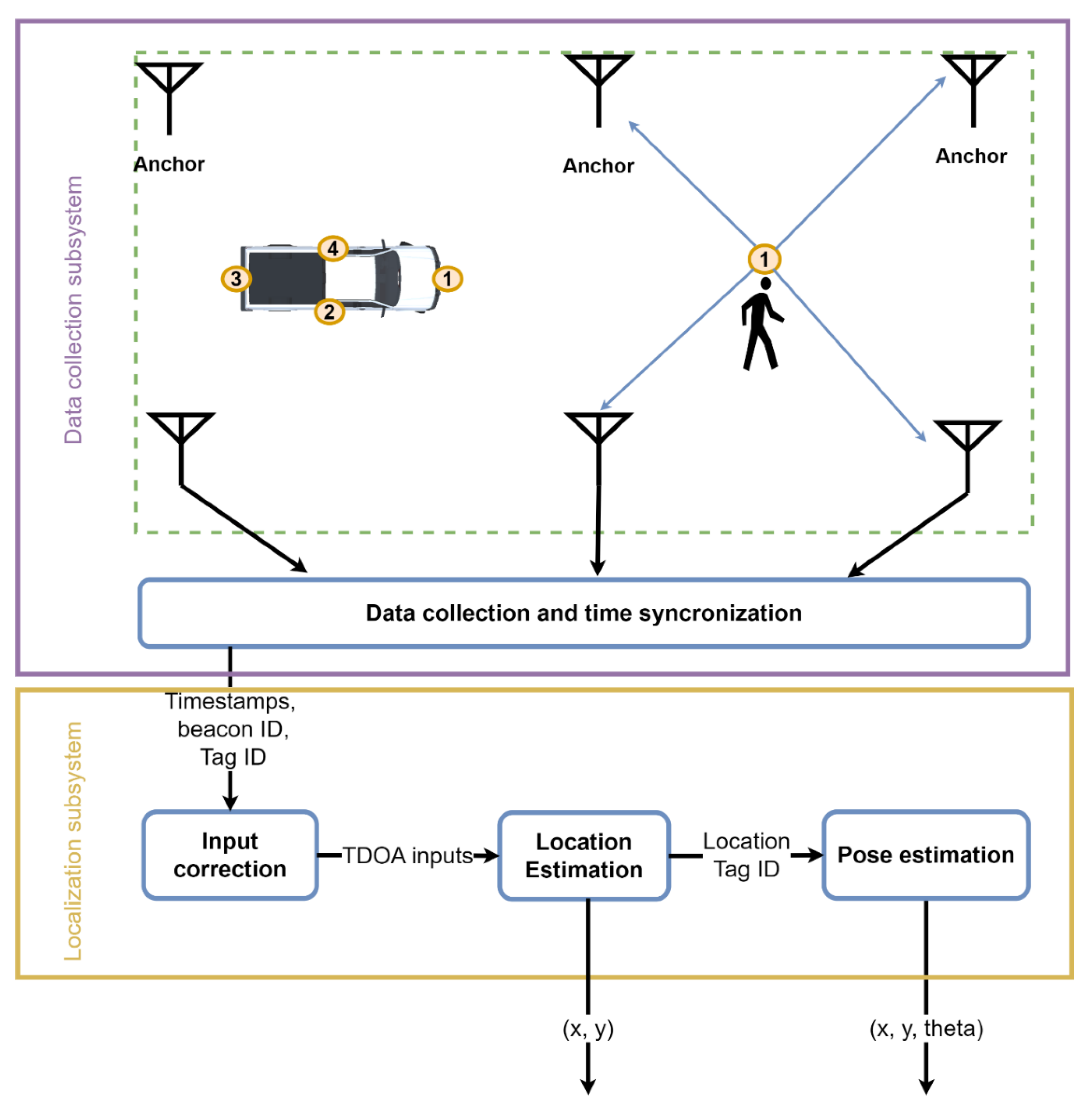
4.1. Data Collection Subsystem

ViPER+ uses the Time of Arrival (TOA) of the UWB packets to estimate where the tag is located. In all TOA approaches, the Time Difference of Arrival (TDOA) works best for localization in real-world scenarios due to the smaller number of messages [45]. In TDOA, radio nodes are categorized into two main groups, anchors and tags. Anchors are radios with fixed locations that are known by the system. Tags are usually moving nodes that the TDOA system wants to track. The signal transmitted by the tag is received by anchors. The timestamp of the signal received is calculated by the anchors and reported to the server for localization. To provide a connection between the localization server and anchors, we implemented a WiFi infrastructure that connected all anchors to the server.

4.1.1. Time Synchronization

Besides having anchors and tags, time synchronization is another requirement that is crucial for the operation of TDOA systems. Since anchors are reporting the timestamp of the received signals, all anchors must implement a time synchronization technique to correct the received signal timestamp before using them for localization. A group of TDOA systems uses wired infrastructure to transmit time synchronization messages to anchors. However, wiring all anchors are not plausible in all environments, including construction sites.
Another group of solutions uses wireless radios to provide synchronization which is more feasible in a construction site environment. In this approach, the system assigns an anchor (an external anchor or one of the localization anchors) to be the time sync anchor. This anchor periodically starts a global two-way ranging (TWR) session with other anchors to estimate its distance with anchors and perform time synchronization. The ranging session starts with a time-sync anchor broadcasting a TWR poll (TWR-POLL) message to all anchors. Upon reception of the TWR-POLL message, each anchor replies with a TWR response (TWR-RESP) message. Finally, the time-sync anchor broadcasts the TWR final (TWR-FINAL) message, containing the received timestamp of all TWR-RESP messages, and indicating the end of the ranging session.
Since anchors run on different clock speeds, the time sync anchor needs to perform synchronization periodically throughout the tracking session. In our design, when anchors receive the TWR-FINAL message, they send a report packet containing the content of the TWR-FINAL message along with the transmission timestamp of the TWR-RESP and received timestamp of TWR-POLL and TWR-FINAL to the server.

4.1.2. Tag/Anchor Communication

As we mentioned, tags are entities whose location is tracked by the localization system. In TDOA systems, tags periodically transmit beacon messages using their UWB radio. When anchors receive this message, they send a report packet containing the timestamp of the received packet to the server. In addition to anchors, tags also plan their transmission time by utilizing time synchronization messages. The Time Division Multiple Access (TDMA) approach was used in our tags to send beacon messages to avoid collision between messages. For each tag, our system dedicates a transmission time slot based on the ID of the tag. Then each tag schedules its transmission time according to the time slot and the reception time of the time synchronization message.

4.1.3. Reception Timestamp Correction

The last step in the data collection sub-system is correcting the timestamps that are received from anchors. Every time an anchor reports a time-sync message, the server calculates the clock difference and the clock skew of that specific anchor based on the data of the time-sync report. Upon the reception of beacon packets, the server uses the last clock skew value to adjust the anchor’s clock with the clock of the time sync anchor.

4.2. Localization Subsystem

4.2.1. TDOA Localization

To calculate our tags’ location, the localization subsystem collects the beacon messages from the data collection subsystem. If more than four anchors have reported the reception of a beacon message, the subsystem uses the TDOA estimation method to estimate the tag location. The reference anchor is chosen from one of the anchors using a TDOA estimation approach. Note that the reference anchor is different from the time sync anchor that was used to synchronize the clocks. A non-convex optimizer was given the reference anchor and the other chosen anchors. The optimization solver calculates the optimum location using the location of anchors and the given timestamps. For this process, the TDOA inputs are estimated using the given timestamps. From Equation (1), the TDOA input can be estimated for anchor a denoted as I a , which is the speed of light c, multiplied by difference of each timestamp and the reference anchor’s timestamp. After all the inputs are estimated, the next step is to define an objective function as shown in Equation (2). The parameters used in Equation (2) defined in Table 1.
I a = c × ( t a t r e f )
f ( x ,   y ) = a a n c h o r s ( ( x x a ) 2 + ( y y a ) 2 I a ) 2
The optimizer then estimates the location where the value of the objective function was minimized. In Equation (3), the ( x * , y * ) is the estimated location of the tag.
( x * , y * ) = argmin x , y f ( x , y )  
R e s i d u a l   v a l u e = f ( x * , y * )
In addition to the estimation of the tag, the TDOA algorithm also gives us a value called the residual value. The value of this parameter is calculated according to Equation (4). In an optimum situation where there is no error in any input, this value should be close to 0. Although this value cannot precisely represent the location estimation error, researchers have used this value to enhance the location estimation by removing outputs with high residual values [46].

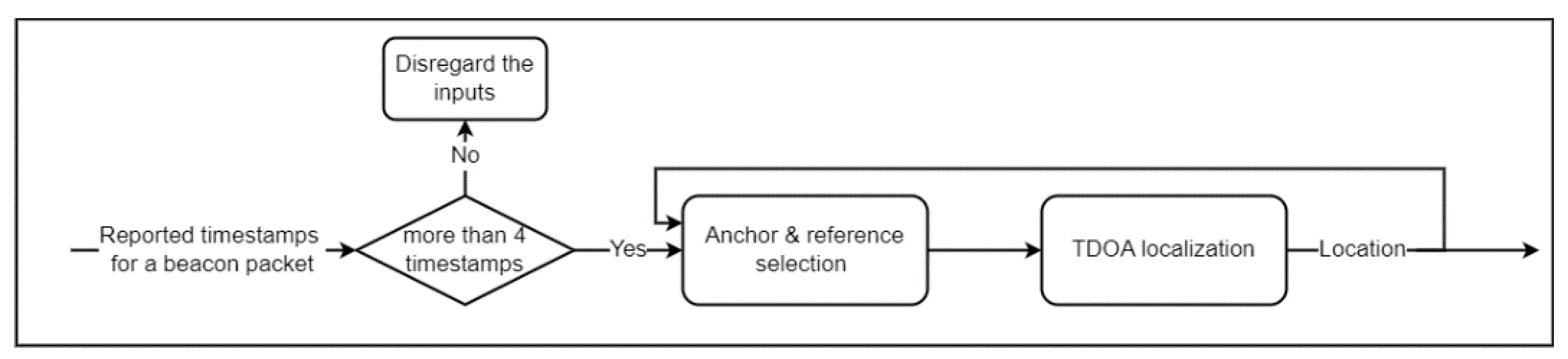
4.2.2. Input Correction and Location Estimation

The accuracy of the location estimation can be significantly impacted by the reference anchor selection [44]. As a result, the reference selection approach in TDOA algorithms seeks to pick the best anchor as the reference with the lowest error in calculating the time of arrival. Besides choosing a reference, the choice of anchors for localization is crucial. The TDOA algorithm needs a minimum of four anchors to report the timestamp of the signals received. The number of reported timestamps may surpass the minimum needed timestamp for localization in system implementations with more than four anchors. Since each anchor received the signal in a different condition, the accuracy of the received timestamp estimation for each signal may change for each anchor. The anchor selection procedure eliminates any anchors that have less precision in estimating the received timestamp.
Several studies have presented various approaches for both anchor and reference selection. Rene et al. [47] proposed a reference selection approach that takes the shortest distance as the reference anchor because inaccurate measurements frequently have longer distances compared to accurate ones. Although this approach may work for some scenarios, it cannot be applied to all environments. Another study [46] compared all feasible inputs that could be used for localization to establish the best choice for anchors and the reference. Though the approach finds the best choice, the process requires a lot of computing effort. Hence, regular computers cannot estimate the location in a reasonable amount of time required for safety monitoring applications with this approach.
Some studies focus on the characteristic of the signal to estimate the accuracy of the reception timestamp. Channel Impulse Response (CIR) is one item of diagnostic information provided by the receiver when the reception is completed. With CIR, applications can determine the phase and amplitude of the received signal during the reception. Some studies [22,48,49,50] used machine learning methods to distinguish corrupted signals. The solutions from these studies need a preliminary dataset that matches the real data for the learning process. For this reason, these solutions are impractical as the training and testing environment might be different. The dynamicity of the environment also causes different types of reception that might not be considered in the training dataset. Another group of studies depended on using statistical methods on CIR [21,51,52,53]. In place of extracting the feature and finding the patterns, these solutions analyze the characteristics of the CIR when the signal is corrupted. As such, the solutions from this group do not need extensive data collection for the training phase. However, researchers have cited that corrupted signals do not always follow the same principles, leading to incorrect error estimation of these solutions [20].
Another group of studies relies on previous inputs for anchor and reference selection. When tags transmit beacon messages at a high rate, this group of solutions claims that the input of the TDOA function is relatively close for two consecutive beacon messages. Thus, these solutions rely on the previous measurements for anchor and reference selection. Wann et al. [54] proposed an approach for correcting two-way ranging using Kalman Filter on the previous results. ViPER [44] applied the same idea for TDOA localization and used a low-pass filter (LPF) to detect and correct corrupted signals. In addition to detecting errors, these solutions provide a degree of correction for erroneous signals. This is beneficial in situations where there are only four TDOA inputs for a beacon packet and the localization engine cannot eliminate any further input.
Using LPF in ViPER requires the whole trace of TDOA inputs for correction. This means that the system needs to know the upcoming inputs for that anchor. To implement this in real-time tracking, the system needs to add an intentional delay before the input correction to collect TDOA inputs that came after the input that the system wants to localize. The amount of this delay depends on the requirement of the application and sometimes it is impossible to add this delay. The correction method is also unable to correct the TDOA input of an anchor if there is missing data for that anchor. The presence of large machines can block anchors and prevent them from receiving beacon messages. These gaps reduce the performance of these solutions, making them not practical for real-time location tracking.
Our new solution for input correction replaces LPF with an exponentially weighted moving average (EWMA) to eliminate the requirement for future TDOA input. To handle missing TDOA inputs, our new approach tries to synthesize the missing data instead of disregarding incomplete inputs. This allows the input correction method to be more robust against scenarios with anchors being blocked. Figure 2 describes the architecture of our new correction method. Like ViPER, our correction method collects the timestamps from anchors as one of the inputs. If the number of timestamps for a beacon packet is less than four, the system does not have enough data to localize the beacon packet, thus, it will discard the timestamp for that beacon packet. Instead of disregarding incomplete inputs, we are only eliminating inputs that we are unable to localize.
To handle the missing data point, our approach uses the last location of the tag to generate the TDOA inputs from the previous input. In addition to the inputs from anchors, we also import the final location of the tag which is the latest output of the localization subsystem. Having the previous location allows us to approximate the values of the TDOA inputs for the previous beacon message and replace those approximations with the missing TDOA inputs.
For the anchor and reference selection method in our approach, we first select an anchor as the reference anchor and calculate the TDOA inputs for each timestamp using Equation (1). Then, the correction method uses EWMA to correct the errors of the current TDOA input. Equation (5) describes the correction method. In this equation, I a c u r r e n t represents the current TDOA input, and I a p r e v i o u s is the previous TDOA input for anchors a . For anchors that failed to report the received signal’s timestamp, we used the previous value as the current value.
I a c o r r e c t = I a c u r r e n t + ( 1 ) I a p r e v i o u s = 0.8
Once all the corrected inputs are calculated, the anchor and reference selection method estimate the residual value based on the corrected input. If the residual value is within an acceptable range (in our case under 10), the correction method reports the calculated location of the tag. Otherwise, the algorithm chooses another anchor as the reference and repeats the process until the error falls below the threshold. If the system was unable to obtain the desired residual error after trying all anchors as a reference, the system terminates the localization without any result. Since there is no one-to-one mapping between the residual value and localization estimation error, we empirically tuned this threshold for our system.

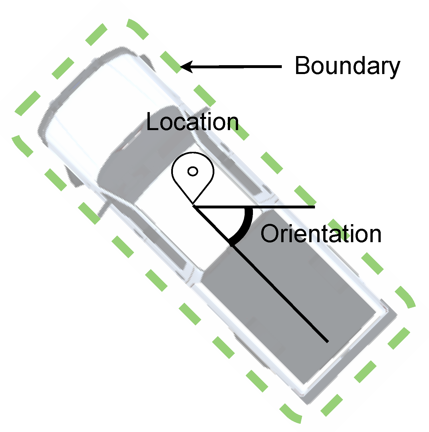
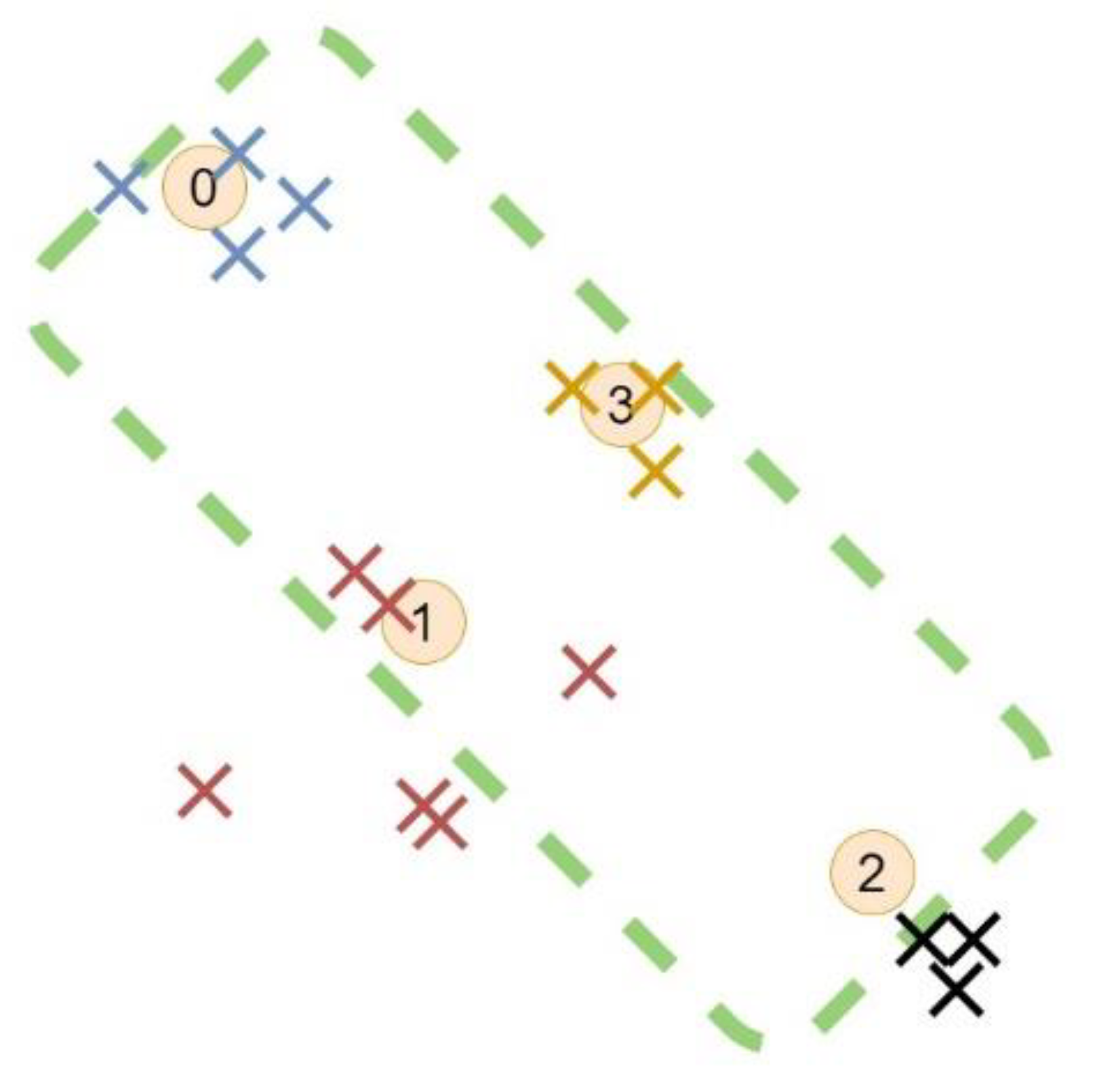
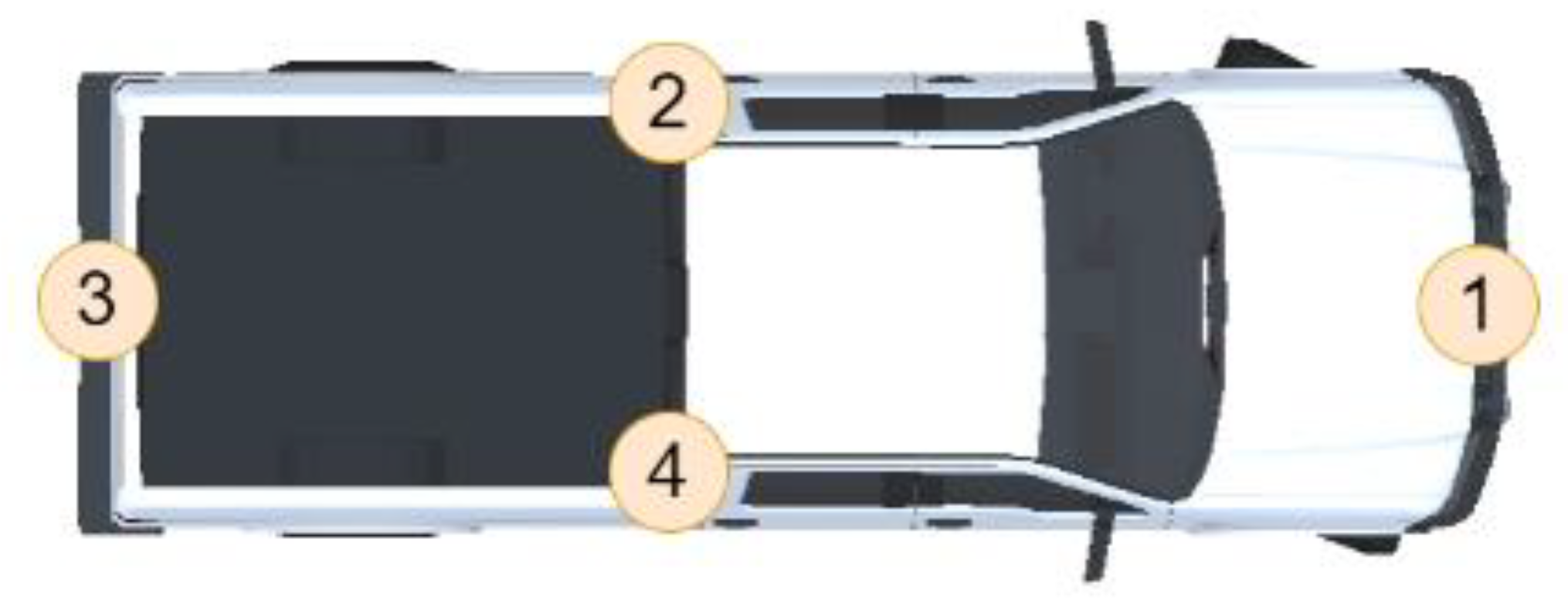
4.2.3. Pose Estimation

Pose estimation is used to calculate the boundary of large equipment and vehicles with several tags affixed to them. This is because reporting a single location is insufficient for all entities in proximity detection applications. Figure 3 shows an illustrated image of the pose of the vehicle. Like the vehicle, the pose of other equipment can be denoted with pairing of location and orientation ( ( x , y ) , θ ) .
Figure 4 shows how the pose estimation was carried out in this study. Two inputs are required for pose estimation. The first input is the equipment’s physical properties, that is, the equipment’s shape (dashed line) and the position of the tags on the object (numbers in circles). The position of the output from the localization subsystem is the second input. The boundary of the object is used to make the pose estimation by aligning the two inputs. The difficulty in this approach is that the locations of the tags do not perfectly align with their placements such as tags 1 and 2. To address this difficulty, we created an objective function described in Equation (6).
f ( x , y , θ ) = i T j s i z e i ( X i x i , j ) 2 + ( Y i y i , j ) 2
( X i ,   Y i ) is calculated based on Equation (7)
[ X i Y i ] = [ c o s ( θ ) s i n ( θ ) s i n ( θ ) c o s ( θ ) ] × [ p x , i p y , i ] + [ x y ]
The remaining parameters are estimated using Table 2. Using this function, the distance between the location of the tags in a given boundary and the estimated locations for that tag can be calculated. To determine the best boundary that aligns the input point, the boundary ( x * , y * , θ * ) with minimum value must be identified. The boundary can be determined by solving a non-linear optimization problem. This means that the boundary of the vehicle is the output of the optimization problem.

5. Deployment and Evaluation

In this part, the performance of ViPER+ was evaluated and compared to previous solutions. Since our work is focused on construction site environments, the solution was implemented in a road construction site as an example of a real-world environment.

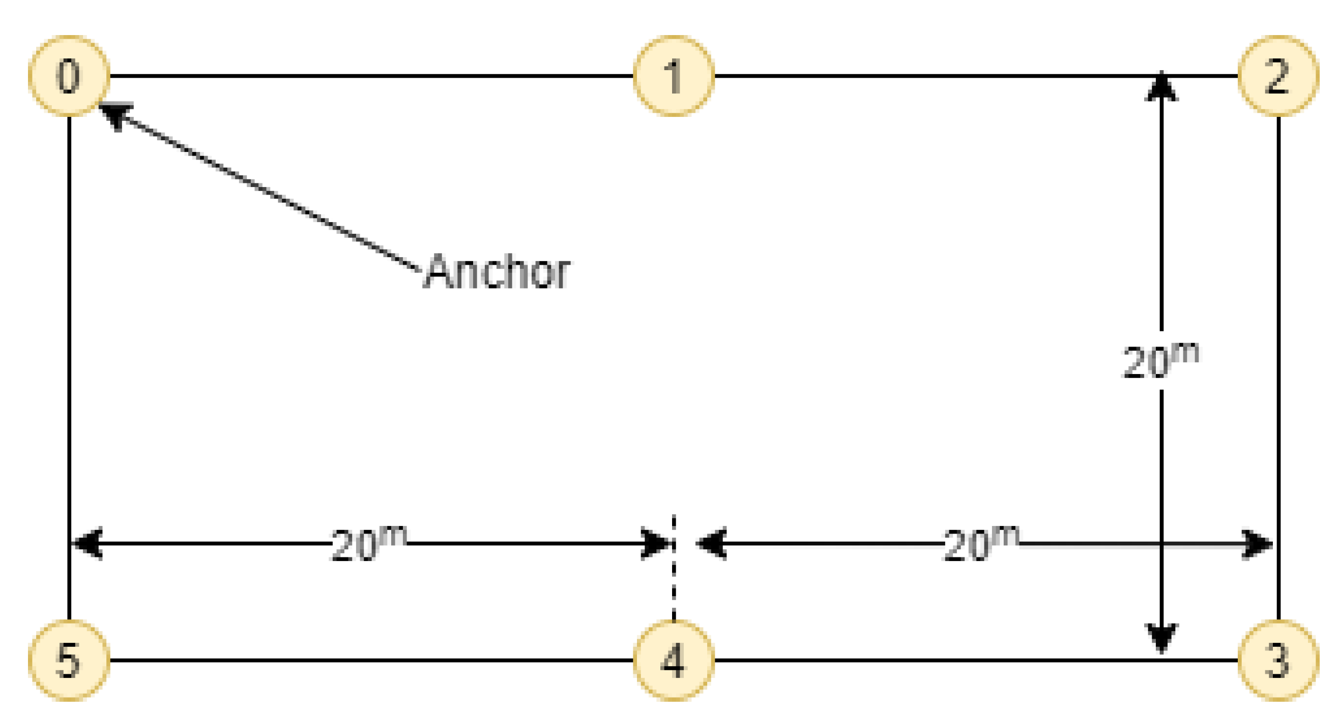
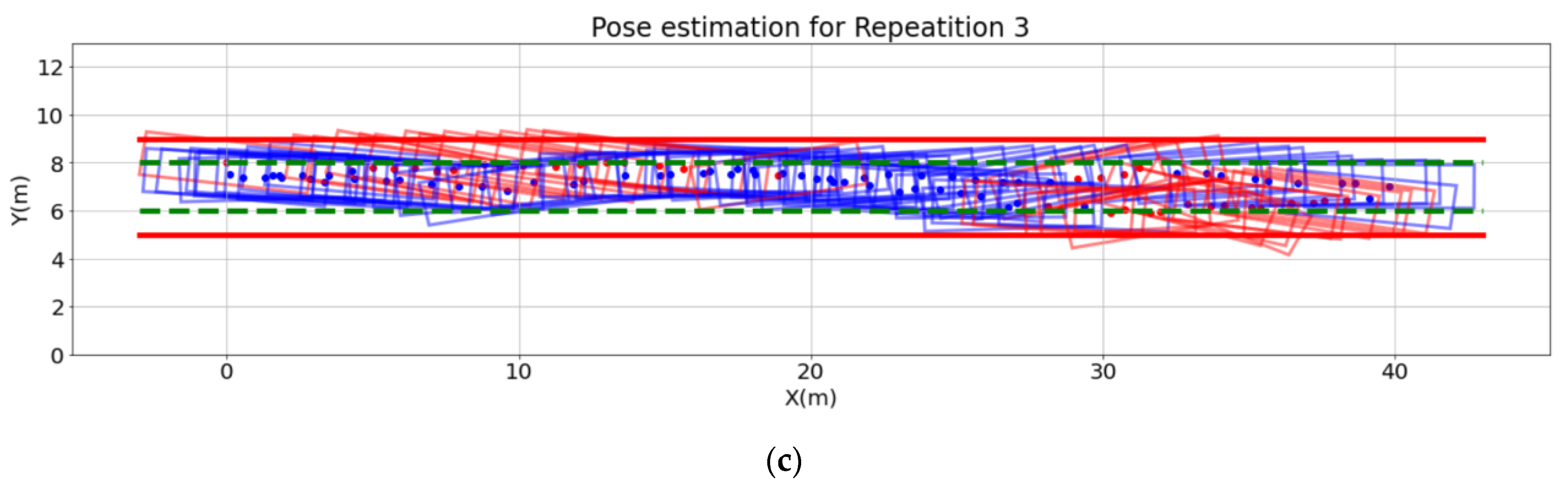
5.1. Experiment Setup

We dedicated a 40 × 20 m field illustrated in Figure 5 to track the vehicles and workers. Six anchors from 0 to 5 are placed on the perimeter of the field.
Our evaluation falls into two main categories, worker tracking, and vehicle tracking. For each category, we conducted multiple scenarios where entities move in a predefined trajectory. In some scenarios, we added a bulldozer to block and distort the transmitted signals to anchor 4. We then compared the results of vehicle tracking and worker tracking for scenarios with and without the presence of the bulldozer.

5.2. Implementation

As we mentioned, UWB radios and an in-circuit radio L4 radio module were used to implement our solution for UWB communication. This radio chip uses the DW1000 radio chip as the UWB interface along with an STM32 micro-controller for managing the radio chip and other interfaces. Raspberry pi running Rasbian was used to monitor UWB anchors. The anchors were connected to the server for data communication using a WiFi infrastructure. The data from the anchors are collected and processed on a DELL Precision 7720 acting as the server. The data flow from anchors is also monitored using the server to ensure their functionality. The TDMA approach used in the tags for transmission allows the location of tags to be updated at 0.2 s intervals.

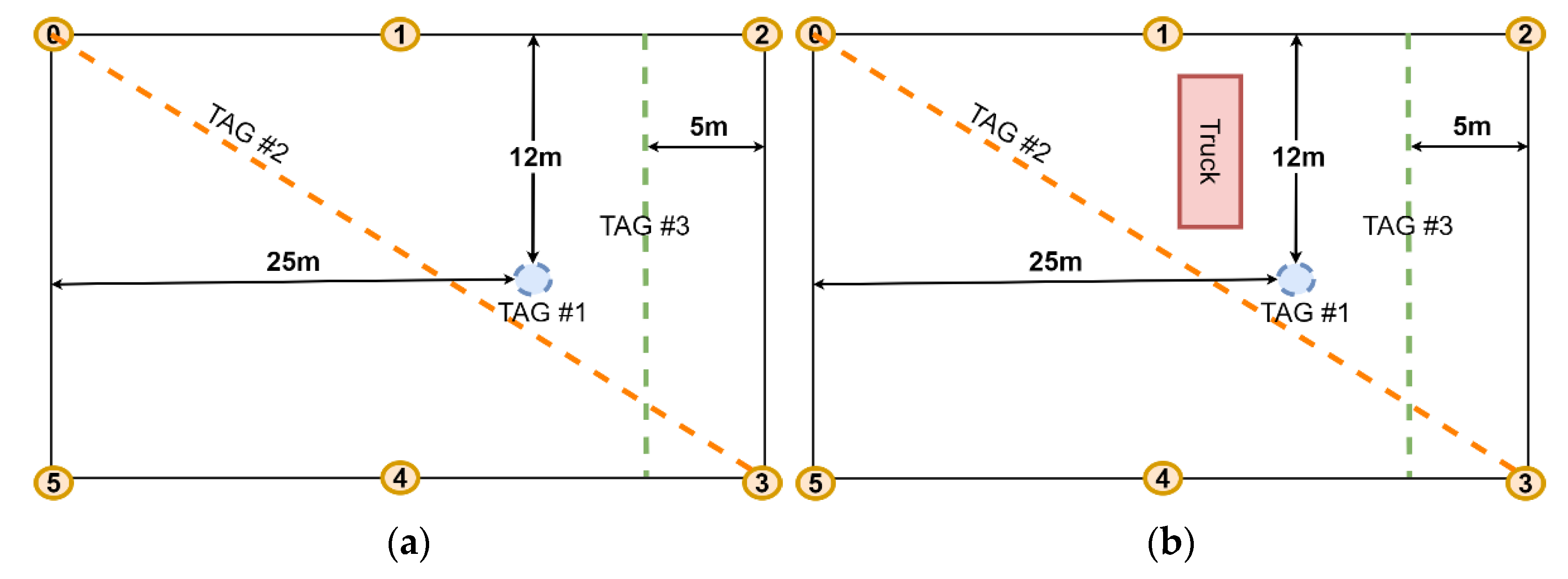
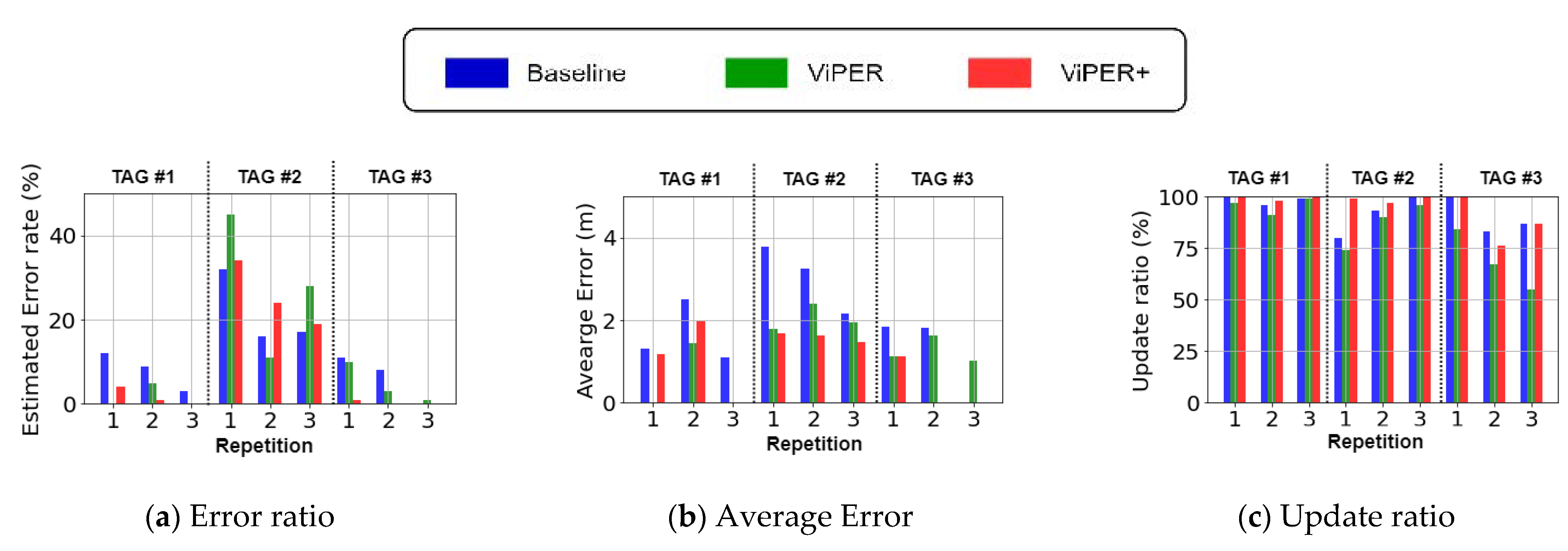
5.3. Evaluation Criteria

For this section, the parameters used to evaluate the performance of our solution are defined. As we mentioned in Section 1, two factors need to be considered that are important in safety tracking systems. First, the system should continuously monitor the entities, and the time interval between two measurements should not exceed more than a certain time. The second important parameter in our study is the error in estimating the location. Inaccurate pose and location estimates can lead to either negative false or positive false alarms in the system. Thus, we need to evaluate the estimation error of each pose estimation method as another evaluation parameter.
The update ratio defines the ratio of time the system can calculate the location. As we explained in Section 5.2, there is a 0.2-s time interval between two consecutive pose updates. If the total tracking time is divided into timeslots of 0.2 s, the ratio of time the system needs to compute the calculated pose for the entity is the update ratio.
Since all our operators for both worker and vehicle tracking were human, their location or pose may not completely align with the ground truth. We considered 1 m as the error threshold in our work. If the distance between the estimated location or pose and the ground truth is less than 1 m, we interpret that estimation as a correct pose/location estimate. Otherwise, it will mark it as an incorrect estimation. The error ratio represents the ratio of incorrect estimation among all the pose/location estimates throughout the trajectory of the worker or the vehicle. The average error is also the average distance of incorrect measurements from the ground truth.

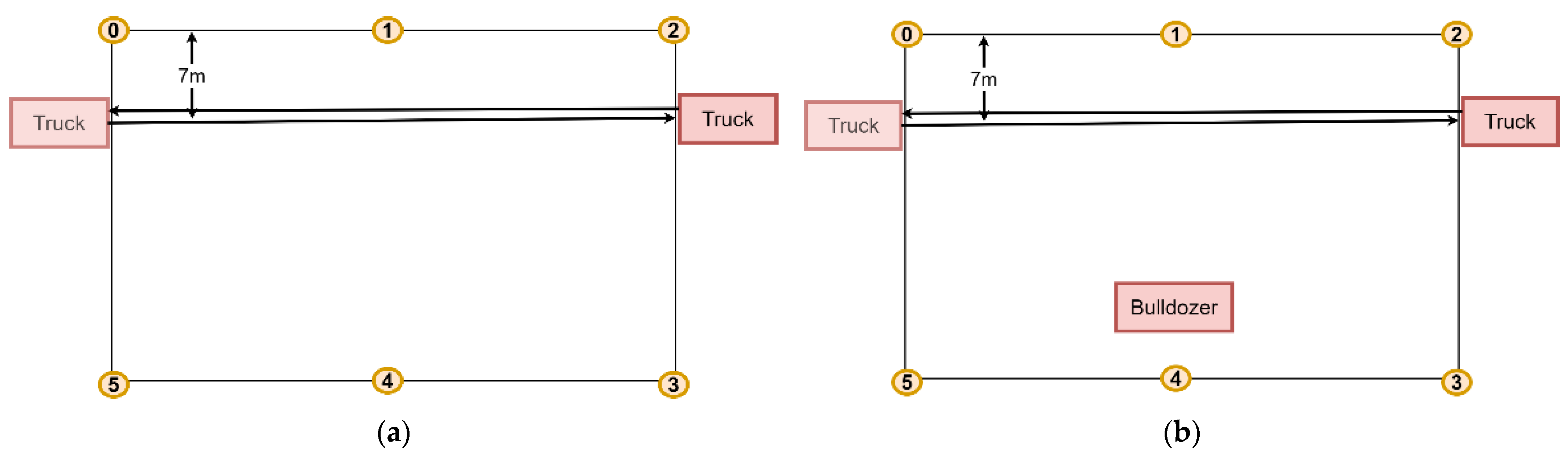
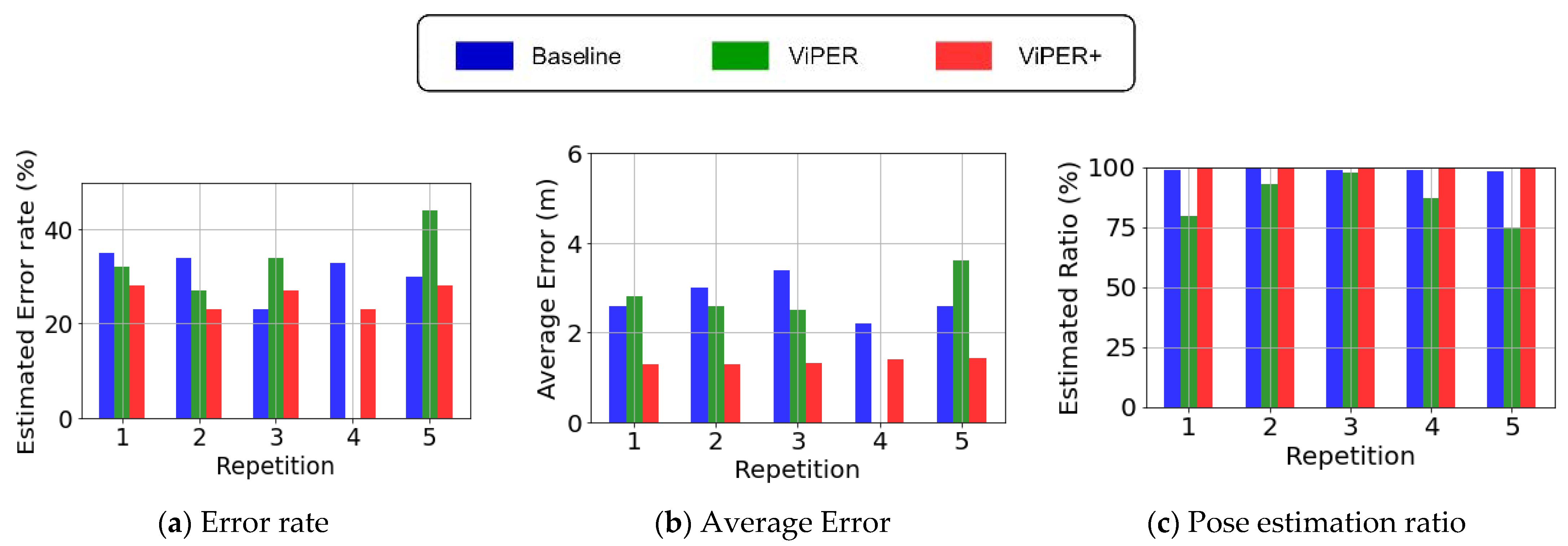
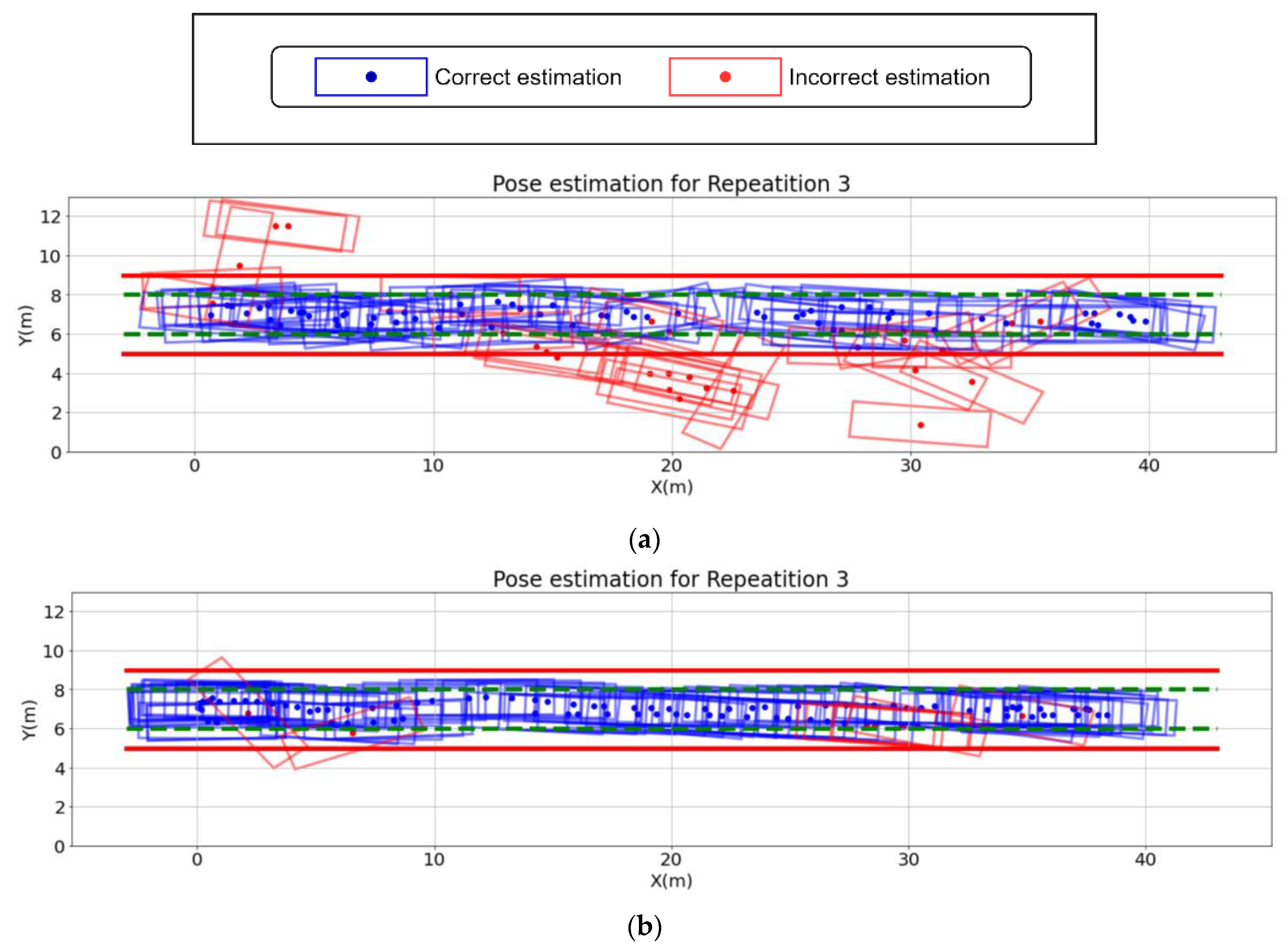
5.4. Pose Estimation for Vehicle Tracking

The error and update ratio for vehicle pose estimation is evaluated in this section. Four tags were placed on the body of the vehicle to track its pose. Figure 6 displays the tag placement for the vehicle used in the experiment.
Figure 7 shows the trajectory of the truck moving from the right of the tracking zone to the left. To measure the impact of blocking objects, we placed a bulldozer in front of anchor 4.
The first group of our analysis focused on the LOS scenario. Table 3 shows the average estimated error ratio, average error, and update ratio of the three proposed methods, and Figure 8 illustrates these values for each repetition.
When estimating the pose in scenarios without blocking objects, the LPF error correction method and the optimization-based pose estimation method introduced in ViPER reduced the error rate compared to the baseline method by 15% while providing a close update ratio. ViPER+ was also able to reduce the error ratio and average error compared to the baseline method and have the lowest average error among all other methods.
We summarize the results of the scenario with blocking object (NLOS) in Table 4 and Figure 9. According to the results, NLOS signals have different impacts in each pose estimation method. In the baseline method, the number of estimation errors increased. In ViPER, in addition to higher error rates, the update ratio dropped by nearly 10% in the NLOS scenario. The presence of the bulldozer prevented the anchor from capturing all the signals from the tags. This increased the number of incomplete inputs which caused problems when estimating the pose with ViPER. According to Figure 9c, in the NLOS scenario, ViPER had a lower update ratio compared to the baseline.
Since ViPER+ solved the problem of incomplete inputs in ViPER, we observed that this method provided the highest update ratio and lowest error ratio, and average error compared to previous methods. In some cases, such as repetition #3 in the LOS scenario, ViPER+ had an equal or higher error ratio compared to the baseline. Figure 10 depicts the output for repetition #3 of the LOS scenario using all the pose estimation methods. We marked the incorrect estimates with a different color to distinguish them from the correct estimates.
According to Figure 10b, ViPER had the lowest pose estimation error rate in estimating the pose of the vehicle. In Figure 10c, although the number of incorrect estimates is high, estimated poses are closer to the ground truth pose compared to the incorrect estimates estimated with the baseline method in Figure 10a. Depending on the input, the ViPER+ input correction may not reduce the error to less than a meter. However, reducing the average error is beneficial for applications that can tolerate more error thresholds.

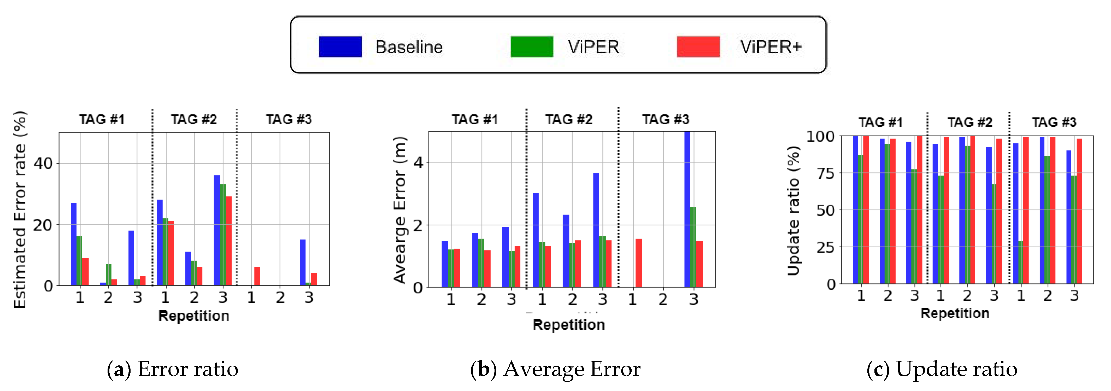
5.5. Single Tag Localization for Worker Tracking

As we mentioned, safety tracking systems also track the location of workers. We also dedicated two scenarios for worker tracking. Figure 11 shows the two scenarios we used for worker tracking. Similar to vehicle tracking, we used a truck (in Figure 11b) to create obstructions in some scenarios. For this scenario, we placed a static tag (TAG #1) and two tags (TAG #2 and #3) traversing the trajectories marked with dashed line in Figure 11a,b.
The results in Table 5 and Table 6 show that the error rate increased for both static tags and moving tags when an object was blocking some signals, creating an NLOS situation. In the baseline method, the error rate increases by 11% for the static tag (tag #1) in the NLOS situation. The results in Figure 12c and Figure 13c show that in both LOS and NLOS scenarios, ViPER was unable to provide a sufficient update ratio in some repetitions due to incomplete inputs.
With ViPER+ for localization of the tags, we achieved the same update rate as the baseline method, while having a low error ratio and average error as ViPER.

6. Discussion

This study presented a pose estimation system designed for monitoring construction safety. We conducted a real-world evaluation of our system in a road construction setting, where trucks and loaders cause NLOS conditions and obstructions. We compared the performance of our proposed approach with that of two previous methods for pose estimation. The implementation and testing of our proposed solution was done using the DecaWave DW1000 radio chip on the RadinoL4 platform. The connection to the server and anchors was established using Raspberry Pi devices. Most of our evaluation scenarios were designed to highlight situations where ViPER struggled to perform sufficiently. We observed that the presence of heavy construction equipment leads to obstruction of the signals. This makes location/pose unavailable in ViPER due to generating incomplete inputs. This lack of availability is not acceptable in real-time monitoring systems because it could result in a significant number of missed alarms if the status of all entities is not continuously tracked. In ViPER+, we redesigned the input correction method to accept TDOA inputs with missing anchors to eliminate the incomplete input limitation in ViPER.
ViPER+ has a limitation on the maximum number of tags that the system can track simultaneously. To prevent packet corruption, only one tag can broadcast a message at a time in our design. For this reason, the maximum number of tags that could be monitored in ViPER+ is limited to 40 tags at this time. One way to increase the number of tags is reconfiguring UWB radios to operate in different channels. DW1000 supports seven channels for configuration. Four of these channels can operate simultaneously without jeopardizing the communication on the other three channels. In addition, pulse repetition frequency (PRF) is another parameter in UWB radio configuration. Similar to channel, PRFs can also create isolated UWB links enabling concurrent communication. DW1000 supports PRF 16 and 64. With four different channels and two different PRFs, we can scale the maximum number of tags eight times (320 tags) for safety applications requiring more tags.
The distance between the entities and the anchors is another limitation of our approach. The assumption in ViPER+ is that all the entities are in an area known as the tracking zone that is surrounded by anchors. When an entity is not within the tracking zone, there is no guarantee that the error rate and update rate requirement for that entity will be addressed by the system. Future studies on this subject will concentrate on the development and testing of an alerting system for the interaction between the server and the entities. In addition, the system needs to alert users about their situations and aid them in avoiding unsafe situations.

7. Conclusions

This study developed, implemented, and tested a vehicle pose estimation system for safety monitoring in construction environments. Previous wireless radio-based pose estimation systems were not able to provide the required level of accuracy and pose reception rate needed for safety monitoring solutions. In ViPER+, these two essential factors in pose estimation were improved making it possible to use our solution for safety monitoring in construction sites. A series of case studies for worker and construction vehicle tracking situations under LOS and NLOS conditions were studied for our proposed improvements in this study. Our results show a 40% average error reduction and a 25% improvement in update ratio compared to ViPER for vehicle pose estimation in an environment with a blocking object. These improvements show the potential of our proposed input correction and pose estimation techniques in improving the performance of safety tracking systems.

Author Contributions

Conceptualization, K.K., O.G.; methodology, O.G., A.A., M.H.; software, A.A., M.H.; validation, A.A.; writing—original draft preparation, K.K., A.A.; writing—O.G., H.O.; visualization, A.A.; funding acquisition, K.K., O.G. All authors have read and agreed to the published version of the manuscript.

Funding

The research reported in this publication was supported by the National Cooperative Highway Research Program (NCHRP) Idea of the National Academy of Sciences under the award NCHRP-206. All the contents are from Gnawali, O. and K. Kim. Rule-Based Automated Safety Monitoring System for Work Zone Safety, Final report for NCHRP IDEA Project 206, Transportation Research Board, Washington, DC, USA, 2022. https://onlinepubs.trb.org/onlinepubs/IDEA/FinalReports/Highway/NCHRP206.pdf (accessed on 27 November 2022). Copyright, National Academy of Sciences. Reproduced with permission of the Transportation Research Board.

Institutional Review Board Statement

Not applicable.

Informed Consent Statement:

Not applicable.

Data Availability Statement

Not applicable.

Conflicts of Interest

The authors declare no conflict of interest.

References

  1. Commonly Used Statistics | Occupational Safety and Health Administration. Available online: https://www.osha.gov/data/commonstats (accessed on 27 November 2022).
  2. Highway Work Zone Safety | NIOSH | CDC. Available online: https://www.cdc.gov/niosh/topics/highwayworkzones/default.html (accessed on 27 November 2022).
  3. Pegula, S. Workplace Safety and Health Fatal Occupational Injuries at Road Construction Sites, 2003-07. Available online: https://www.jstor.org/stable/monthlylaborrev.2010.11.037 (accessed on 27 November 2022).
  4. Regulations (Standards - 29 CFR) | Occupational Safety and Health Administration. Available online: https://www.osha.gov/laws-regs/regulations/standardnumber (accessed on 27 November 2022).
  5. Work Zone Safety Consortium Developing Internal Traffic Control Plans (ITCPs) for Work Zones. 2016. Available online: https://workzonesafety-media.s3.amazonaws.com/workzonesafety/files/documents/training/courses_programs/rsa_program/RSP_Guidance_Documents_Download/RSP_ITCP_Guidance_Download.pdf (accessed on 27 November 2022).
  6. Graham, J.L.; Burch, R. Internal Traffic Control Plans and Worker Safety Planning Tool. Transp. Res. Rec. 2006, 1948. [Google Scholar] [CrossRef]
  7. Albert, A.; Hallowell, M.R.; Kleiner, B.M. Enhancing Construction Hazard Recognition and Communication with Energy-Based Cognitive Mnemonics and Safety Meeting Maturity Model: Multiple Baseline Study. J. Constr. Eng. Manag. 2013. [Google Scholar] [CrossRef]
  8. Bahn, S. Workplace Hazard Identification and Management: The Case of an Underground Mining Operation. Saf. Sci. 2013, 57, 129–137. [Google Scholar] [CrossRef]
  9. Carter, G.; Smith, S.D. Safety Hazard Identification on Construction Projects. Constr. Eng. Manag. 2006, 132, 197–205. [Google Scholar] [CrossRef]
  10. Park, J.; Kim, K.; Cho, Y.K. Framework of Automated Construction-Safety Monitoring Using Cloud-Enabled BIM and BLE Mobile Tracking Sensors. J. Constr. Eng. Manag. 2017, 143, 05016019. [Google Scholar] [CrossRef]
  11. Park, J.; Chen, J.; Cho, Y.K. Self-Corrective Knowledge-Based Hybrid Tracking System Using BIM and Multimodal Sensors. Adv. Eng. Informatics 2017, 32, 126–138. [Google Scholar] [CrossRef] [Green Version]
  12. Carbonari, A.; Giretti, A.; Naticchia, B. A Proactive System for Real-Time Safety Management in Construction Sites. Autom. Constr. 2011, 20, 686–698. [Google Scholar] [CrossRef]
  13. Teizer, J.; Venugopal, M.; Walia, A. Ultrawideband for Automated Real-Time Three-Dimensional Location Sensing for Workforce, Equipment, and Material Positioning and Tracking. Transp. Res. Rec. J. Transp. Res. Board 2008, 56–64. [Google Scholar] [CrossRef]
  14. Fang, Y.; Cho, Y.K.; Zhang, S.; Perez, E. Case Study of BIM and Cloud–Enabled Real-Time RFID Indoor Localization for Construction Management Applications. J. Constr. Eng. Manag. 2016. [Google Scholar] [CrossRef]
  15. Park, J.; Marks, E.; Cho, Y.K.; Suryanto, W. Performance Test of Wireless Technologies for Personnel and Equipment Proximity Sensing in Work Zones. J. Constr. Eng. Manag. 2015, 142, 4015049. [Google Scholar] [CrossRef]
  16. Lu, M.; Chen, W.; Shen, X.; Lam, H.-C.; Liu, J. Positioning and Tracking Construction Vehicles in Highly Dense Urban Areas and Building Construction Sites. Autom. Constr. 2007, 16, 647–656. [Google Scholar] [CrossRef]
  17. Vahdatikhaki, F.; Hammad, A.; Siddiqui, H. Optimization-Based Excavator Pose Estimation Using Real-Time Location Systems. Autom. Constr. 2015. [Google Scholar] [CrossRef]
  18. Silva, B.; Pang, Z.; Åkerberg, J.; Neander, J.; Hancke, G. Experimental Study of UWB-Based High Precision Localization for Industrial Applications. In Proceedings of the Ultra-WideBand (ICUWB), Paris, France, 1–3 September 2014; pp. 280–285. [Google Scholar]
  19. Decawave None Line of Sight Operations and Optimizations to Improve Performance in DW1000 Based Systems. Available online: https://www.qorvo.com/products/d/da008450 (accessed on 27 November 2022).
  20. Heydariaan, M.; Mohammadmoradi, H.; Gnawali, O. Toward Standard Non-Line-of-Sight Benchmarking of Ultra-Wideband Radio-Based Localization. In Proceedings of the Proceedings-2018 1st Workshop on Benchmarking Cyber-Physical Networks and Systems, CPSBench 2018. Porto, Portugal, 10–13 April 2018. [Google Scholar]
  21. Gururaj, K.; Rajendra, A.K.; Song, Y.; Law, C.L.; Cai, G. Real-Time Identification of NLOS Range Measurements for Enhanced UWB Localization. In Proceedings of the 2017 International Conference on Indoor Positioning and Indoor Navigation, IPIN 2017. Sapporo, Japan, 18–21 September 2017. [Google Scholar]
  22. Yu, K.; Wen, K.; Li, Y.; Zhang, S.; Zhang, K. A Novel NLOS Mitigation Algorithm for UWB Localization in Harsh Indoor Environments. IEEE Trans. Veh. Technol. 2019. [Google Scholar] [CrossRef]
  23. Li, X.; Wang, Y. Research on the UWB/IMU Fusion Positioning of Mobile Vehicle Based on Motion Constraints. Acta Geod. Geophys. 2020, 1–19. [Google Scholar] [CrossRef]
  24. Strohmeier, M.; Walter, T.; Rothe, J.; Montenegro, S. Ultra-Wideband Based Pose Estimation for Small Unmanned Aerial Vehicles. IEEE Access 2018, 6, 57526–57535. [Google Scholar] [CrossRef]
  25. Barral, V.; Suárez-Casal, P.; Escudero, C.J.; García-Naya, J.A. Multi-Sensor Accurate Forklift Location and Tracking Simulation in Industrial Indoor Environments. Electronics 2019, 8, 1152. [Google Scholar] [CrossRef] [Green Version]
  26. Mikov, A.; Moschevikin, A.; Voronov, R. Vehicle Dead-Reckoning Autonomous Algorithm Based on Turn Velocity Updates in Kalman Filter. In Proceedings of the 27th Saint Petersburg International Conference on Integrated Navigation Systems, ICINS 2020-Proceedings. St. Petersburg, Russia, 25–27 May 2020. [Google Scholar]
  27. Zhang, R.G.; Shen, F.; Li, Q.H. A Hybrid Indoor/Outdoor Positioning and Orientation Solution Based on INS, UWB and Dual-Antenna RTK-GNSS. In Proceedings of the 2020 27th Saint Petersburg International Conference on Integrated Navigation Systems (ICINS), St. Petersburg, Russia, 25–27 May 2020; pp. 1–5. [Google Scholar]
  28. Li, M.G.; Zhu, H.; You, S.Z.; Tang, C.Q. UWB-Based Localization System Aided with Inertial Sensor for Underground Coal Mine Applications. IEEE Sens. J. 2020. [Google Scholar] [CrossRef]
  29. Han, Y.; Wei, C.; Li, R.; Wang, J.; Yu, H. A Novel Cooperative Localization Method Based on IMU and UWB. Sensors 2020, 20, 467. [Google Scholar] [CrossRef] [Green Version]
  30. Competent Person - Overview | Occupational Safety and Health Administration. Available online: https://www.osha.gov/competent-person (accessed on 27 November 2022).
  31. Sulankivi, K.; Kähkönen, K.; Mäkelä, T.; Kiviniemi, M. 4D-BIM for Construction Safety Planning. In Proceedings of the W099-Special Track 18th CIB World Building Congress, Manchester, UK, 10–13 May 2010; 2010; pp. 117–128. [Google Scholar]
  32. Zhang, S.; Teizer, J.; Lee, J.-K.; Eastman, C.M.; Venugopal, M. Building Information Modeling (BIM) and Safety: Automatic Safety Checking of Construction Models and Schedules. Autom. Constr. 2013, 29, 183–195. [Google Scholar] [CrossRef]
  33. Kim, K.; Cho, Y.K.; Zhang, S. Integrating Work Sequences and Temporary Structures into Safety Planning: Automated Scaffolding-Related Safety Hazard Identification and Prevention in BIM. Autom. Constr. 2016, 70, 128–142. [Google Scholar] [CrossRef]
  34. Lee, U.-K.; Kim, J.-H.; Cho, H.; Kang, K.-I. Development of a Mobile Safety Monitoring System for Construction Sites. Autom. Constr. 2009, 18, 258–264. [Google Scholar] [CrossRef]
  35. Cheng, T.; Venugopal, M.; Teizer, J.; Vela, P.A. Performance Evaluation of Ultra Wideband Technology for Construction Resource Location Tracking in Harsh Environments. Autom. Constr. 2011, 20, 1173–1184. [Google Scholar] [CrossRef]
  36. Shahi, A.; Aryan, A.; West, J.S.; Haas, C.T.; Haas, R.C.G. Deterioration of UWB Positioning during Construction. Autom. Constr. 2012, 24, 72–80. [Google Scholar] [CrossRef]
  37. Esmaeilnejad, S. Accuracy Assessment of UWB RTLS for Tracking Resources on Construction Sites; University of Calgary: Calgary, AB, Canada, 2015. [Google Scholar]
  38. Wang, J.; Raja, A.K.; Pang, Z. Prototyping and Experimental Comparison of IR-UWB Based High Precision Localization Technologies. In Proceedings of the Ubiquitous Intelligence and Computing and 2015 IEEE 12th Intl Conf on Autonomic and Trusted Computing and 2015 IEEE 15th Intl Conf on Scalable Computing and Communications and Its Associated Workshops (UIC-ATC-ScalCom), Beijing, China, 10–14 August 2015; pp. 1187–1192. [Google Scholar]
  39. Hwang, S. Ultra-Wide Band Technology Experiments for Real-Time Prevention of Tower Crane Collisions. Autom. Constr. 2012, 22, 545–553. [Google Scholar] [CrossRef]
  40. Pittokopiti, M.; Grammenos, R. Infrastructureless UWB Based Collision Avoidance System for the Safety of Construction Workers. In Proceedings of the 2019 26th International Conference on Telecommunications, ICT 2019. Hanoi, Vietnam, 8–10 April 2019. [Google Scholar]
  41. Ghanem, E.; O’Keefe, K.; Klukas, R. Estimating Vehicle-to-Vehicle Relative Position and Attitude Using Multiple UWB Ranges. In Proceedings of the CEUR Workshop Proceedings, Victoria, BC, Canada, 18 November 2020–16 December 2020. [Google Scholar]
  42. Wang, M.; Zhou, A.; Chen, X.; Shen, Y.; Li, Z. A Novel Asynchronous UWB Positioning System for Autonomous Trucks in an Automated Container Terminal. SAE Tech. Pap. 2020, 2, 3413–3422. [Google Scholar] [CrossRef]
  43. Zhang, C.; Hammad, A.; Rodriguez, S. Crane Pose Estimation Using UWB Real-Time Location System. J. Comput. Civ. Eng. 2012, 26, 625–637. [Google Scholar] [CrossRef] [Green Version]
  44. Ansaripour, A.; Heydariaan, M.; Gnawali, O.; Kim, K. ViPER: Vehicle Pose Estimation Using Ultra-Wideband Radios. In Proceedings of the 2020 16th International Conference on Distributed Computing in Sensor Systems (DCOSS), Marina del Rey, CA, USA, 25–27 May 2020. [Google Scholar]
  45. Hara, S.; Anzai, D.; Yabu, T.; Lee, K.; Derham, T.; Zemek, R. A Perturbation Analysis on the Performance of TOA and TDOA Localization in Mixed LOS/NLOS Environments. IEEE Trans. Commun. 2013, 61, 679–689. [Google Scholar] [CrossRef]
  46. Xu, Q.; Lei, Y.; Cao, J.; Wei, H. An Improved Algorithm Based on Reference Selection for Time Difference of Arrival Location. In Proceedings of the 2014 7th International Congress on Image and Signal Processing, Dalian, China, 14–16 October 2014; pp. 953–957. [Google Scholar] [CrossRef]
  47. Rene, J.E.; Ortiz, D.; Venegas, P.; Vidal, J. Selection of the Reference Anchor Node by Using SNR in TDOA-Based Positioning. In Proceedings of the 2016 IEEE Ecuador Technical Chapters Meeting (ETCM), Guayaquil, Ecuador, 12–14 October 2016; pp. 1–4. [Google Scholar] [CrossRef]
  48. Maranò, S.; Gifford, W.M.; Wymeersch, H.; Win, M.Z. NLOS Identification and Mitigation for Localization Based on UWB Experimental Data. IEEE J. Sel. Areas Commun. 2010, 28, 1026–1035. [Google Scholar] [CrossRef]
  49. Yang, X. NLOS Mitigation for UWB Localization Based on Sparse Pseudo-Input Gaussian Process. IEEE Sens. J. 2018, 18, 4311–4316. [Google Scholar] [CrossRef]
  50. DecaWave Evk1000 User Manual How To Use, Configure and Interface To the Dw1000. 2013, 1–21. Available online: https://datasheet.octopart.com/EVK1000-Decawave-datasheet-86813690.pdf (accessed on 27 November 2022).
  51. Guvenc, I.; Chong, C.C.; Watanabe, F. NLOS Identification and Mitigation for UWB Localization Systems. IEEE Wirel. Commun. Netw. Conf. WCNC 2007, 1573–1578. [Google Scholar] [CrossRef]
  52. Heidari, M.; Pahlavan, K. Identification of the Absence of Direct Path in ToA-Based Indoor Localization Systems. Int. J. Wirel. Inf. Networks 2008, 15, 117–127. [Google Scholar] [CrossRef]
  53. Mucchi, L.; Marcocci, P. A New Parameter for UWB Indoor Channel Profile Identification. IEEE Trans. Wirel. Commun. 2009, 8, 1597–1602. [Google Scholar] [CrossRef]
  54. Wann, C.D.; Hsueh, C.S. NLOS Mitigation with Biased Kalman Filters for Range Estimation in UWB Systems. In Proceedings of the TENCON 2007–2007 IEEE Region 10 Conference, Taipei, Taiwan, 30 October 2007–2 November 2007. [Google Scholar] [CrossRef]
Figure 1. Overview of ViPER+.
Applsci 13 01581 g001
Figure 2. Overview of the TDOA input correction in ViPER+.
Applsci 13 01581 g002
Figure 3. The defined boundary of vehicles in ViPER+.
Applsci 13 01581 g003
Figure 4. The pose estimator estimates the boundary by aligning the positions of the mounted tags on the vehicle (circles) with the calculated locations (cross).
Applsci 13 01581 g004
Figure 5. The anchor placement around the tracking zone.
Applsci 13 01581 g005
Figure 6. Tag placement for vehicle pose estimation.
Applsci 13 01581 g006
Figure 7. Vehicle tracking for scenarios (a) without blocking objects and (b) with a blocking object.
Applsci 13 01581 g007
Figure 8. Results of vehicle tracking for scenarios without blocking objects. Using ViPER reduces the error rate in the pose estimation of the vehicle compared to the other two methods.
Applsci 13 01581 g008
Figure 9. Results of vehicle tracking for scenarios with a blocking object. Using ViPER reduces the error rate in the pose estimation of the vehicle compared to the other two methods.
Applsci 13 01581 g009
Figure 10. Pose estimation output for repetition #3 of LOS scenario (a) baseline, (b) ViPER, and (c) ViPER+.
Applsci 13 01581 g010aApplsci 13 01581 g010b
Figure 11. Worker tracking for scenarios (a) without blocking objects and (b) with blocking object. Dashed lines represent the trajectory of each worker carrying a tag and the dashed circle shows the static tag.
Applsci 13 01581 g011
Figure 12. Worker tracking results for scenarios without blocking objects (LOS).
Applsci 13 01581 g012
Figure 13. Worker tracking results for scenarios with blocking objects.
Applsci 13 01581 g013
Table 1. Parameters of the objective function.
ParametersDescription
( x a , y a ) Location of anchor a
(x, y)Location of the tag
I a TDOA input for anchor a
Table 2. Parameter table for pose estimation optimizer.
ParametersDescription
(x, y)Location of the vehicle
θ Orientation of the vehicle
TNumber of tags mounted on the vehicle
s i z e i Number of locations from tag i
( x i , j ,   y i , j )jth location of tag i
( p x , i ,   p y , i ) Position of tags relative to the center of the vehicle
Table 3. Pose estimation result for LOS scenario. ViPER+ provided the same update rate as the baseline method while reducing the error rate and average error compared to the baseline.
Pose Estimation MethodEstimated Error Ratio (%)Average Error (m)Update Ratio (%)
Baseline243.499
ViPER92.695
ViPER+191.699
Table 4. Pose estimation result for NLOS scenario. ViPER+ provided the same update rate as the baseline method while reducing the error rate and average error compared to the baseline.
Pose Estimation MethodEstimated Error Ratio (%)Average Error (m)Update Ratio (%)
Baseline312.898
ViPER272.386
ViPER+261.499
Table 5. The results of worker tracking for LOS scenario without blocking object.
Localization
Method
Estimated Error Ratio (%)Average Error (m)Update Ratio (%)
Static TagMoving TagsStatic TagMoving TagsStatic TagMoving Tags
Baseline8121.329993
ViPER2110.51.39684
ViPER+291.119995
Table 6. The results of worker tracking for NLOS scenario with blocking object.
Localization
Method
Estimated Error Ratio (%)Average Error (m)Update Ratio (%)
Static TagMoving TagsStatic TagMoving TagsStatic TagMoving Tags
Baseline19151.72.29796
ViPER9101.31.28675
ViPER+591.21.29999
Disclaimer/Publisher’s Note: The statements, opinions and data contained in all publications are solely those of the individual author(s) and contributor(s) and not of MDPI and/or the editor(s). MDPI and/or the editor(s) disclaim responsibility for any injury to people or property resulting from any ideas, methods, instructions or products referred to in the content.

