Whether you’re designing and building a one- or two-story single-family residence, or doing the same for a multifamily, mid-rise wood-frame structure, fire and smoke protection features must be considered, and in most cases are required. When a fire starts, time is of the essence and the longer the flame and gases can be contained and the spread of the fire to adjacent spaces is kept in check, the greater the chance firefighters and first responders will have to defeat the blaze. Though many building jurisdictions have slightly different requirements and provisions, the three primary modes of fire rating that codes consider are an F-rating (flame), a T-rating (temperature rise), and an L-rating (air or gas leakage). The F and T ratings are gauged on a resistance per hour basis and the L rating is based on a rating of air leakage in cubic feet per minute per square foot of opening, or CFM/sq.ft. These ratings and provisions are in place to help safeguard against the spread of fire and smoke within the immediate structure as well as to contain the spread of fire to other structures.
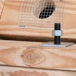
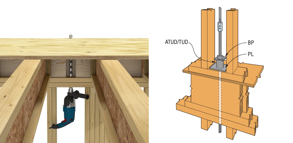
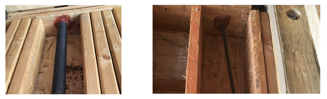
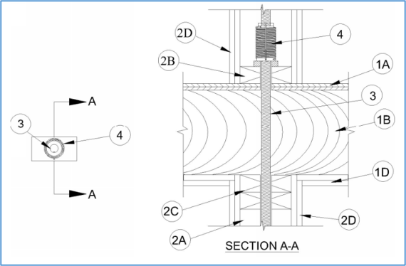
It is standard, and quite necessary, that penetrations exist throughout a structure, where ventilation ducts, plumbing pipes, electrical conduits and countless other utilities snake up, down and through the framing of the building. Not unlike the utility penetrations, many traveling from the first floor to the top floor, the continuous rod system runs vertically beginning at the foundation level and terminates at the roof line or within the wall of the uppermost floor. As the rod remains continuous within the wall cavity (between the framing studs), drilled penetrations through the sill plate, subfloor and double top plate are necessary so the rod can travel the entire building height.
The continuous rod is part of a series of components that provide the tension capacity for the lateral-force-resisting system to help maintain structural stability during a seismic event. Many building jurisdictions require that the rod penetrations that are necessary for the system, be sealed after the rod is installed so that flame, temperature and gas propagation can be kept to a minimum.
Traditional Means of Firestopping
For years, the most common means of closing a penetration within a wall or floor system has been to apply generous amount of fire caulking that cures around the hole like dried bubble gum or Play-Doh. When installed to the manufacturer’s specifications, that application produces a reliable firestop. This substance comes in two main forms, including flowable tubes or large buckets where the caulk can be applied with a putty knife. Some fire caulking products remain malleable after they’re applied, while many of the products cure to a brittle hardness.
Though the benefits of a sound firestop as the rod travels through the slightly oversized drilled thru-hole are necessary, there are several downsides to adhering this substance to the rod as it intersects with the wood framing. Understanding that in continuous rod systems, the rod remains static while the building shrinks as the wood loses moisture content, any interference preventing the wood from shrinking past the rod can become a problem. Some of these concerns include:
- A hard cure on the threads of the rod can prevent the wood framing from cleanly traveling down over the rod as the building shrinks. The grip on the rod caused by the fire caulking can lead to the buckling of rods, which in turn can lead to the take-up devices being ineffective.
- Fire caulking that cures and hardens inside the take-up device can damage the moving components and could cause the device to be ineffective.
- Some fire caulking can be corrosive to metal, and when this is the case, any contact with the steel or aluminum components and devices could cause corrosion.
These concerns, in addition to the cost in time and money of applying fire caulking to every penetration for a continuous rod system, have led us to design alternative means for a code-acceptable through-penetration firestop system using the Simpson Strong-Tie RTUDs or ATUDs combined with their associated bearing plates.
Code References
So where do we go for guidance on understanding when fire and smoke protection are needed? Well, in many cases, it is dependent on what provisions your building department has adopted. Both the 2018 International Building Code® (IBC®) and the 2018 International Residential Code® (IRC®) give guidance on fire-resistance ratings, fire tests, combustibility, through-penetrations, fire retardant lumber, sprinklering, and many other fire protection variables and scenarios. The particular sections in the codes that most building departments will refer to when requiring penetration firestop systems are the following:
- 2018 IBC, Section 714.4.1.2, Through-penetration firestop system. This portion of the code indicates that through-penetrations shall be protected by an approved penetration firestop system installed as tested in accordance with ASTM E814 or UL 1479, with a minimum positive differential of 0.01 inch of water and shall have an F rating of not less than the required fire-resistance rating of the wall penetrated.
- 2018 IBC, Section 714.2, Installation, which indicates that a listed penetration firestop system shall be installed in accordance with the manufacturer’s installation instructions and the listing criteria.
- 2018 IRC, Section R302.4.1.2, which provides the exact same guidance as the IBC section 714.4.1.2.
The testing standards that the IBC and IRC refer to are ASTM E814 and UL 1479, both of which are the standards that typical building fire caulking generally comply with. In summary, these two standards give direction on:
- ASTM E814: Standard Test Method for Fire Tests of Penetration Firestop Systems.
- This test method is applicable to firestop systems of various materials and construction. The standard notes that firestop systems are intended for use in openings in fire-resistive walls and floors.
- UL 1479: Standard for Fire Tests of Through-Penetration Firestops. This UL standard requires successful testing of all approved through-penetration firestops designed for use in penetrations in firewalls of floor, and floor-ceiling assemblies. Though this is a UL standard, UL laboratories also refer to ASTM E814 as a standard testing procedure.
- CAN/ULC S115: Canadian Standard for Fire Tests of Through-Penetration Firestops
Within the IBC, IRC, ASTM E814 and UL 1479, there are several terms that are frequently used when describing and referencing firestop systems and ratings. A few of those are:
- Through-Penetration Firestop System: An assemblage consisting of a fire-resistance-rated floor, floor-ceiling, or wall assembly that has one or more penetrating items passing through breaches in the assembly, along with materials or devices, or both, that have installed to resist the spread of fire through the assembly for a prescribed period of time.
- Membrane Penetration Firestop: A material, device or construction installed to resist for a prescribed time period the passage of flame and heat through openings that have been made in a protective membrane to accommodate the passage of cables, cable trays, conduit, tubing, pipes or similar items.
- F-Rating Firestop: The time period that the through-penetration firestop system limits the spread of fire through the penetration when tested in accordance with ASTM E814 or UL 1479.
- T-Rating Firestop: The time period that the penetration firestop system, including the penetration item, limits the maximum temperature rise through the penetration to 325ºF (163ºC) above its initial temperature on the non-fire side when tested in accordance with ASTM E814 or UL 1479.
- L-Rating Firestop: The air leakage rating of a through-penetration firestop system or a fire-resistant joint system when tested in accordance with UL 1479 or UL 2079, respectively.
Consulting and Testing
Now how do we go about investigating whether our Simpson Strong-Tie take-up devices and bearing plates can be a means to an adequate through-penetration firestop system? Well, we began by consulting various fire protection engineers; understanding and reviewing our system; becoming more acquainted with how other products achieve fire ratings; and understanding how our system would be tested to the various standards. Following this extensive consultation and investigative phase, we reached out to Underwriters Laboratories (UL) to inquire about the feasibility of using our Simpson Strong-Tie take-up devices and associated bearing plates as a means to achieving a two-hour rating for flame, temperature and gas. Agencies such as UL define tests and standards to determine an hour rating for how long a building system can adequately resist flame propagation and smoke generation without providing additional fuel for combustion. We worked with their labs on an initial study, and it was determined that the system should be tested to establish specified fire ratings.
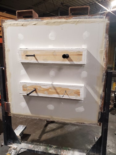
From there, setup layouts and drawings were drafted, all following the guidelines of UL 1479 and ASTM E814. In order to attain data and eventual fire-rating coverage on multiple-hour rating assemblies, the lab technicians then constructed setups that are consistent with the wood-framed floor-ceiling assemblies per UL and ASTM Standards.
Both two-hour and one-hour floor-ceiling assemblies were constructed in a manner and with materials specified in the UL Fire Resistance Directories. Specifically:
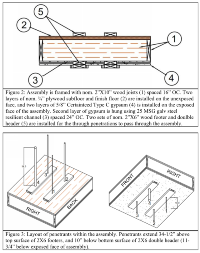
- Floor System: Lumber and plywood subfloor with finish floor of lumber and plywood as with a round penetration that was 1/4″ larger than the specified rod diameter.
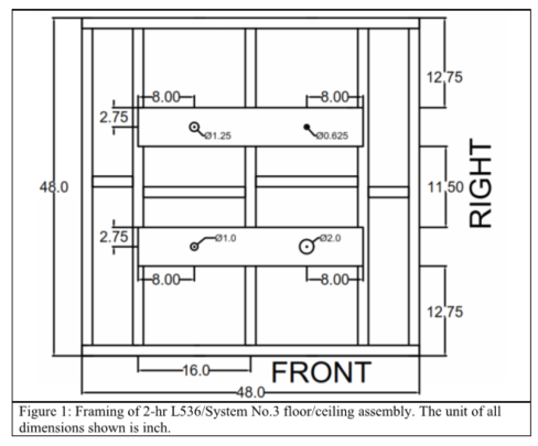
- Wood Joists: The tested assembly for two-hour fire-rated floor-ceiling assemblies was equivalent to a system with 2×10 lumber joists spaced at 16″c. with nominal 1×3 lumber bridging and with ends fireblocked.
- Gypsum Board: Nominal 48″ x 5/8″-thick gypsum board secured to wood joists as specified in the individual floor-ceiling design. The maximum ceiling opening was 1/4″ larger than the specified rod diameter.
- Sole Plate and Top Plate: The simulated sole plate and top plates were built using 2x members and framed in a manner that most closely simulated a typical floor system.
Other specifics of the setups included the following:
- 2-Hour Assembly
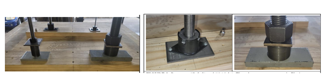
- Parts used: RTUD3B, RTUD8, ATUD6-2 and ATUD14
- Threaded rods: Rods were placed through the oversized round floor penetrations and matched specified diameters associated with the devices
- Setup assembly: Two layers of gypsum board for the ceiling
- 1-Hour Assembly
- Parts used: RTUD8 and ATUD14
- Threaded rods: Same as for 2-Hour assembly
- Setup assembly: One layer of gypsum board for the ceiling
- General
- Temperature gauges
- Moisture content and relative humidity gauges
- Adhering pads to secure the temperature gauge wires to the take-up device, rods, and wood framing
- Support brackets for hoisting the assembly
Firestop System Testing
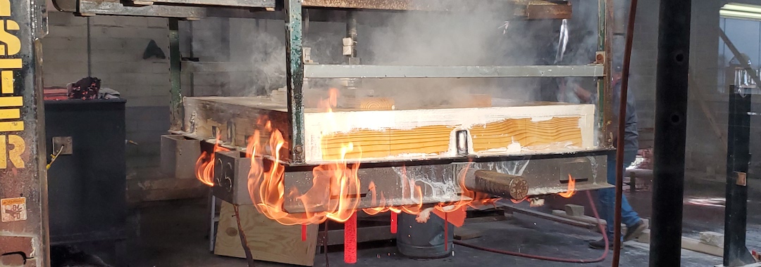
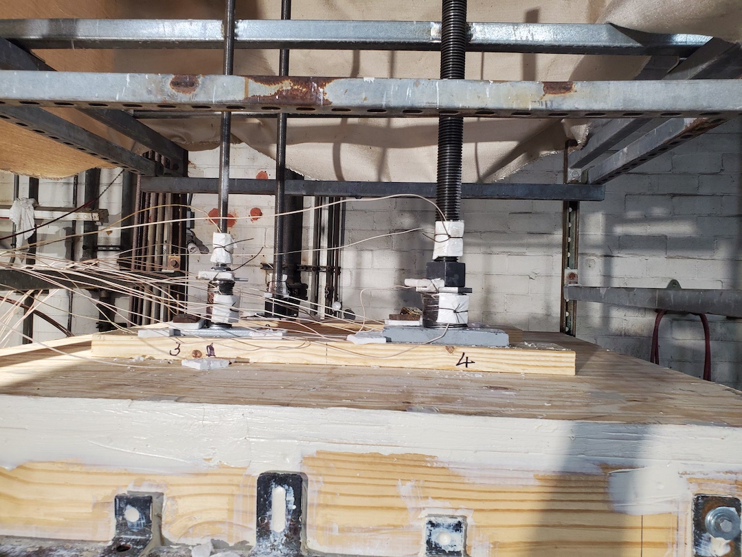
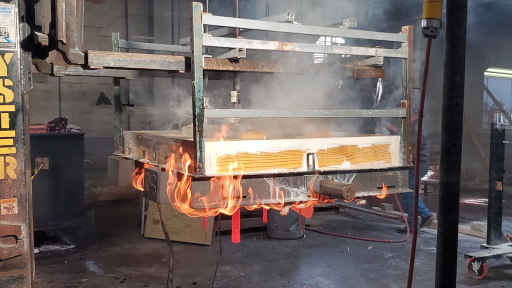
After setups were approved, checked and back-checked, the simulated floor systems were ready to be tested. When we say tested, we mean that they were now ready to be intentionally set on fire. The means of starting the blaze was a furnace with burners whose intensity and temperature could be controlled manually. Both two-hour and one-hour tests were conducted, where the floor assemblies spent the respective amount of time in the furnace burners and temperature, gas and moisture levels were gauged as well as visual observations made.
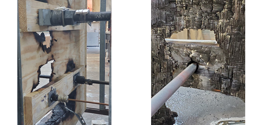
During the testing of the two-hour assembly, smoke vented from the devices for the first 15 minutes of the test. Shortly after this first 15 minutes, smoke stopped venting, though gas continued to steam slowly through the RTUD8 during the test. Flame did not pass through the devices until the very end of the test when the lab technicians began taking the assembly off. According to the techs, this did not occur until after the burner was turned off which essentially was the end of our test. Judging by this information, the pass-through flames were not a result of the take-up devices, and all devices passed the measured criteria, though the RTUD8 required additional evaluation. There is a maximum temperature each component can reach and this temperature cannot be exceeded for the entire two hours; the RTUD8 exceeded the temperature at one hour and 58 minutes. With respect to the wood framing and gypsum board, both layers of the gyp were burned through, and the floor sheathing had larger burn holes after being sprayed with a power water hose; however, the bearing plates where the take-up devices were placed were still intact. Note that the water power spray to conclude the test is part of the testing protocol where the hose stream is measured, and exposure time recorded. For this two-hour test, the hose stream was at 30 psi and the setup was sprayed for 24 seconds. Observations after the hose spray did not reveal any openings created by the spray nor was there evidence of water passing through the assembly.
In the one-hour assembly, there was measured air leakage; however, this flow was measured and rated at less than 1 CFM/sq.ft. It should be noted that this value is a ratio of the pressure with and without the opening and that anything less than 1 is considered a passing value. With regards to smoke venting, far less smoke was observed from the RTUD8 than during the two-hour test, though there was still some present. Flames did not pass through the devices, and the floor sheathing remained intact after being power sprayed with the water hose, though the gypsum board did partially break apart and was knocked loose following the power spray from the hose. For this one-hour test, the hose stream was at 30 psi and the setup was sprayed for 10 seconds. The hose spray did not reveal any evidence of water passing through the assembly.

Firestop Testing Conclusions
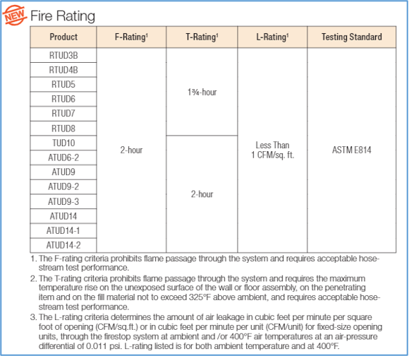
The take-up devices and bearing plates all performed well in both the one-hour and two-hour tests as well as in the air leakage tests. There was more smoke venting from the RTUD devices than the ATUD devices, particularly from the 1″ RTUD8 device; however, this did not result in fire penetrating the devices. It was observed that the ATUD’s top bearing plate aided in sealing the system; however, the RTUD also prevented flame from penetrating the floor system. As concluded by the UL labs, and as a result of their thorough independent analysis of the test data and observations, the Simpson Strong-Tie take-up devices and bearing plates now comply with the UL’s applicable requirements, were found suitable for use in one- and two-hour locations, and are now listed under UL Fire Resistance Directory R40313. The take-up device assembly with bearing plates provides UL-listed fire protection for F, T, and L ratings without the need to install costly and time-consuming fire caulking after installation of the take-up device, and the hour ratings are summarized here:
UL website: https://iq.ulprospector.com/en
Advantages of the System
The take-up device and bearing plate assembly eliminates concerns that are often associated with traditional fire caulk when the substance adheres to the rods and affects the mechanics of the device, which could restrict rod travel and device functionality. As discussed here, the assembly has been tested to the same ASTM and UL standards as typical building fire caulk.
With the Simpson Strong-Tie take-up devices (RTUD, TUD, and ATUD) and associated bearing plates now being rated as UL-qualified through-penetration firestop systems (UL Fire Resistance Directory R40313), the need is now eliminated for additional fire resistance material at the hole in the wood plates and flooring system.